|
 

|
Please visit our partner in EU
www.duplexers.eu
 | | Electrical specifications
| Model |
W3DZZ+5
|
| Operating frequency band, MHz |
|
| 80 m VSWR no more 2 |
3.5-3.8 MHz
|
| 40 m VSWR no more 2 |
7.0-7.2 MHz
|
| 20 m VSWR no more 2 |
14.0-14.35 MHz
|
| 15 m VSWR no more 1,5 |
21,0-21,32 MHz
|
| 10 m VSWR no more 2 |
28-29,5 MHz
|
| Impedance, Ohm |
50
|
| Connector |
SO-239
|
| Max. power input, W |
1000 (SSB, CW) (300 W for 7 MHz)
|
| Length, m |
36
|
| Weight, kg |
1,9
|
| Material of radiator |
steel brass wire, PVC insulated
|
|
|
| |
The attempts to introduce the three-band dipole w3dzz+3 into the European market led to an interesting acquaintance with a new design of an old antenna which additionally had the bands of 21 and 28 MHz. That design was suggested to me by a well-known Finnish radio amateur Jukka Heikinheimo OH2BR who, in turn, got to know about the modification from his friend OH2EC.
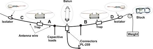
The new antenna is shown in the figure below. Its differences from the predecessor are as follows:
- the antenna is powered through a 1/4 wave transformer with the resistance of 75 Ohm, which improves matching at 14 MHz without considerable decreases in other bands;
- two hanging whiskers at last made it possible to “start” the antenna in the band of 21 MHz with an excellent standing wave ratio;
- the selection of LC - elements in the antenna traps is optimized for a successful compromise of resonances in the bands of 80 m and 20 m.
Antenna W3DZZ+5
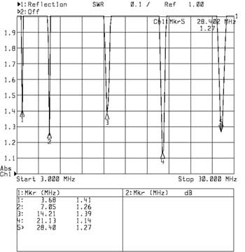
The diagram of standing wave ratio
 |
|
The information provided on this page is not an official offer.
To verify actual parameters contact the sales department before ordering.
|
|