|
 

|
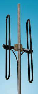
DS2 VHF
|
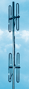
DS4 VHF
|
| | Electrical specifications
| Model |
DS2 VHF |
DS4 VHF |
DS8 VHF
|
| . |
(M) |
(H) |
(M) |
(H) |
(M) |
(H)
|
| Operating frequency band, MHz |
140-163 |
153-177 |
143-163 |
155-177 |
143-163 |
155-177
|
| VSWR, not more than |
1.5
|
| Gain,dBi |
3.15 |
6.15 |
9.15
|
| Sector in vertical plane , -3dB |
86В° |
43В° |
18В°
|
| Impedance, Ohm |
50
|
| Max. power input, W |
500
|
|
|
Mechanical specifications
| Model |
DS2 VHF |
DS4 VHF |
DS8 VHF
|
| Weight, kg |
2.4 |
5.2 |
10.7
|
| Height/Length, M |
0.87 |
2.1 |
4.5
|
| Construction material |
Aluminium alloy
|
| Mast diametr, mm |
35
|
| Rated wind velocity, m/s |
55
|
| Wind loading area, m2 |
0.05 |
0.1 |
0.2
|
| Load of side wind 45 m/s, H |
58 |
116 |
232
|
| Rated wind velocity with 0.5" icing, m/s |
28
|
| Temperature range, В°C |
from -50 to +50
|
| Connector |
N-female
|
| |
Dipole pair DS2 VHF was designed according to special technical specifications, including strict requirements on operating frequency bandwidth, circular pattern, low VSWR, high power conduction, maximum lightning protection and corrosion stability. This construction is the main component for high VSWR antenna array building.
DS4 VHF and DS8 VHF antennas represent array antenna with heightened gain assembled using two or four DS2 VHF antenna pairs connected by adders. These antennas are very easy to transport due to their collapsible construction, in spite of large overall dimension in assembly.
DS2 VHF E-plane pattern
|
DS4 VHF E-plane pattern
|
DS8 VHF E-plane pattern
|
DS2 VHF H-plane pattern
|
VSWR diagram DS2 VHF(M, H)
|
VSWR diagram DS4 VHF(M, H)
|
VSWR diagram DS8 VHF(M, H)
|
|
The information provided on this page is not an official offer.
To verify actual parameters contact the sales department before ordering.
|
|