|
 

|
D2 UHF I
|
D4 UHF I
|
| | Electrical specifications
| Model |
D2 UHF I |
D4 UHF I |
D4 UHF(H)I
|
| Operating frequency band, MHz |
400-490 |
400-490 |
450-540
|
| VSWR, not more than |
1.5 |
1,5 |
1.5
|
| Gain OMNI, dBi |
5.15 |
8.15 |
8.15
|
| OFFSET, dBi |
8.15 |
11.15 |
11.15
|
| Sector in vertical plane -3 dB |
37В° |
18В° |
18В°
|
| Impedance, Ohm |
50 |
50 |
50
|
| Max. power input, W |
200 |
200 |
200
|
|
|
Mechanical specifications
| Model |
D2 UHF I |
D4 UHF I |
D4 UHF(H)I
|
| Weight, kg |
3.5 |
7 |
7
|
| Construction material |
Aluminium alloy
|
| Mast diametr, mm |
38-65
|
| Rated wind velocity, m/s |
55
|
| Wind loading area, m2 |
0.056 |
0.112 |
0.112
|
| Load of side wind, 45 m/s |
64 |
128 |
128
|
| Rated wind velocity with 0.5" icing, m/s |
28
|
| Temperature range, В°C |
from -50 to +50
|
| Connector |
N-female
|
| |
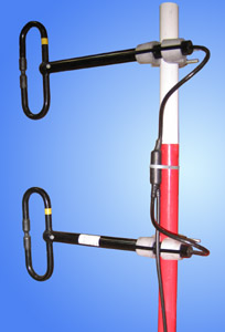
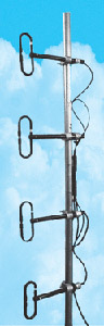
Antenna arrays of series "I" (letter "I" - from "integrated"), namely, D2 UHF I and D4 UHF I consist of two and four dipoles D1 UHF, correspondingly, fixed on a mast and connected by all-soldered cable integrators without connectors. These antennas possess all the advantages of antennas of "D" series: broad operating bandwidth, practically circular radiation pattern, low sensitivity to the noise of industrial origin, the possibility to slightly change the radiation pattern of antenna array in H-plane, the steady polymeric coating. New antennas D2 UHF I and D4 UHF I are remarkable for their enhanced reliability due to all-soldered wiring.
For operating at the frequencies 450-540 MHz we have developed a model D4 UHF(H) I.
These antennas are provided with the detailed SWR graphs for various RP.
VSWR diagram, D2 UHF I
|
VSWR diagram, D4 UHF I
|
VSWR diagram, D4 UHF(H) I
.gif)
|
D1 UHF H-plane pattern, OMNI (1/2О»)
|
D1 UHF H-plane pattern, OFFSET(1/4О»)
.gif)
|
D1 UHF H-plane pattern, OFFSET (1/8О»)
.gif)
|
|
|
The information provided on this page is not an official offer.
To verify actual parameters contact the sales department before ordering.
|
|