 |
 

|

 | Electrical specifications
| Model |
D2 VHF I |
D4 VHF I
|
| Operating frequency band, MHz |
136-174
|
| VSWR, not more than |
1.5
|
| Gain OMNI, dBi |
5.15 |
8.15
|
| OFFSET, dBi |
8.15 |
11.15
|
| Sector in vertical plane , -3dB |
35° |
15-20°
|
| Impedance, Ohm |
50
|
| Max. power input, W |
400 |
400
|
Mechanical specifications
| Model |
D2 VHF I |
D4 VHF I
|
| Weight, kg |
5.2 |
10.4
|
| Height/Length, M |
2.1 |
5
|
| Construction material |
Aluminium alloy
|
| Mast diametr, mm |
40-65
|
| Rated wind velocity, m/s |
45
|
| Wind loading area, m2 |
0.14 |
0.29
|
| Load of side wind 45 m/s, H |
165 |
335
|
| Rated wind velocity with 0.5" icing, m/s |
28
|
| Temperature range, °C |
from -50 to +50
|
| Connector |
N-female
|
| |
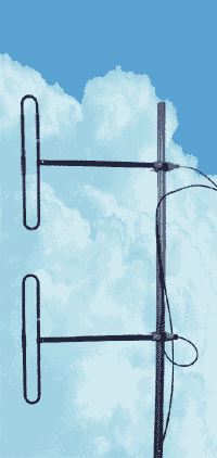
Antenna arrays of series "I" (letter "I" - from "integrated"), namely, D2 VHF I and D4 VHF I consist of two and four dipoles D1 VHF, correspondingly, fixed on a mast and connected by all-soldered cable integrators without connectors. In addition to all the advantages of antennas of "D" series (broad bandwidth, low sensitivity to the noise of industrial origin, the possibility to slightly change the radiation pattern of the antenna array, the steady polymeric coating) an enhanced reliability of the antenna is provided due to all-soldered wiring.
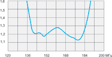
VSWR diagram, D2 VHF I
|
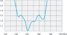
VSWR diagram, D4 VHF I
|
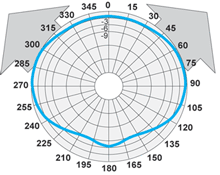
D1 VHF in H-plane, OMNI (1/2λ)
|
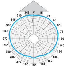
D1 VHF in H-plane, OFFSET (1/4λ)
|
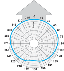
D1 VHF in H-plane, OFFSET (1/8λ)
|
|
The information provided on this page is not an official offer.
To verify actual parameters contact the sales department before ordering.
|
|


