|
 

|
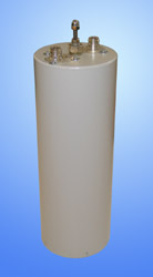
PF4-1A
|
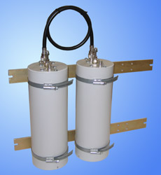
PF4-2A
|
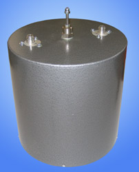
PF10-1A
|
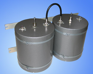
PF10-2A
|
| | Electrical specifications
| Model |
PF4-1A |
PF10-1A
|
| Operating frequency band, MHz |
300-360
|
| Insertion loss (adjustable), dB |
0,5-3
|
| Impedance, Ohm |
50
|
| Attenuation |
see fig.
|
| VSWR, not more than |
1,2
|
| Input power, not more, W |
not more than 300
|
| Temperature range, В°C |
from -30 to +60
|
| Cavity electrical length |
1/4О»
|
|
|
Mechanical specifications
| Model |
PF4-1A |
PF10-1A
|
| Diameter, mm (ins.) |
116 (4") |
257 (10")"
|
| Weight, kg |
1,3 |
2,4
|
| Connector |
N-female
|
| Mount to 19-inch rack |
optional
|
| Dimensions (LxWxH), mm |
110x110x400 |
255x255x400
|
| |
Using PF10-1A filters in antenna section of radio stations and repeaters you will raise selectivity of their receivers, lower influence of out-of-band interference, escape effect of UHF blanking by nearby radio transmitters and desensitization, and eliminate intemodulation interference, also.
Filters, installed in transmitters circuit, lower stray emission level and prevent intermodulation products occurrence. Recommended to use if equipment is installed in locations with high density of transmitting devices.
Typical selectivity characteristics
PF4-1A
|
PF10-1A
|
|
|
The information provided on this page is not an official offer.
To verify actual parameters contact the sales department before ordering.
|
|