|
 

|
RAS-15D-90 (mast mount.)
|
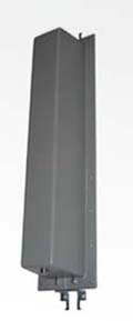
RAS-11D-120 (wall mount.)
|
| | Electrical specifications
| Model |
RAS-11D-120 |
RAS-12D-90 |
RAS-14D-120 |
RAS-15D-90
|
| Operating frequency band, MHz |
1880-1900 |
1880-1900 |
1880-1900 |
1880-1900
|
| Gain,dBi |
11 |
12 |
14 |
15
|
| VSWR, not more than |
1.5 |
1,5 |
1.5 |
1.5
|
| Front-to-back ratio, dB |
22 |
25 |
23 |
25
|
| Polarization |
vertical
|
| Electrical downtilt |
0В° |
0В° |
2В° |
2В°
|
| Max. power input, W |
10 |
10 |
10 |
10
|
| Sector in H-plane (-3 dB) |
120В° |
90В° |
120В° |
90В°
|
| Sector in E-plane (-3 dB) |
17В° |
17В° |
10В° |
9В°
|
| Impedance, Ohm |
50 |
50 |
50 |
50
|
|
|
Mechanical specifications
| Model |
RAS-11D-120 |
RAS-12D-90 |
RAS-14D-120 |
RAS-15D-90
|
| Dimencions (LxWxH), mm |
138x103x580 |
138x103x580 |
138x103x1034 |
138x103x1034
|
| Weight, kg |
1.45 |
1.4 |
2.7 |
2.6
|
| Rated wind velocity, m/s |
40 |
43 |
40 |
43
|
| Radiator |
PCB |
PCB |
PCB |
PCB
|
| Radome |
grey, ABS
|
| Mounting |
on a mast 30-220 mm with "Norma" or CP-55D, CP-115, CP-220
|
| Connector |
N-female on a cable
|
| |
These antennas are assigned for the work within a compound of the base stations while sectoring the servicing area. Due to the increased gain and the standard sectors of the radiation pattern the adequately matched arrays from these antennas will provide the needed traffic and a high range of coverage of the DECT base station. Despite of the existing electrical tilt of the beam which positively influences upon the distribution of the irradiation energetic characteristics within the near-field zone, a mechanical tilt is also possible by means of the mechanism MN-1.
"RAS-120" E-plane pattern
|
"RAS-90" E-plane pattern
|
RAS-11D-120 E-plane pattern
|
RAS-12D-90 E-plane pattern
|
RAS-14D-120 and RAS-15D-90 E-plane pattern
|
|
The information provided on this page is not an official offer.
To verify actual parameters contact the sales department before ordering.
|
|