LLC
Russian versionVersion for print
  • 300-360, 400-490 MHz
    Low-loss transmitter combiners TETRA-A, TETRA-U

    Please visit our partner in EU
    Internet shop www.duplexers.eu
    Catalog www.ik-telecom.com

    TETRA-2U

    TETRA-4U

    Electrical specifications

    Model TETRA-4A TETRA-8A TETRA-2U TETRA-4U TETRA-8U
    Operating frequency band, MHz 300-360 300-360 400-490 400-490 400-490
    Impedance, Ohm 50
    Number of channels 4 8 2 4 8
    Min. space TX/TX, kHz 125
    Insertion loss @ dB@300kHz, dB 3 4.5 2.6 3.4 4.5
    Input power, W 50
    Cavity electrical length 1/4λ
    Isolation TX-TX not less, dB 75
    VSWR not more than1,3
    Temperature Range 30°C to +60°C

    Mechanical specifications

    Model TETRA-4A TETRA-8A TETRA-2U TETRA-4U TETRA-8U
    Weight, kg 15.7 31.9 8 15.2 30.7
    Connector N-female
    Length/Width/Depth, sm 51x49x36 51x49x72 51x49x18 51x49x36 51x49x72

    Taking into account the enhanced demand for 4 and 8 channel trunking systems a combiner has been worked out on the basis of four-resonator monoblock that is mounted at 19" stand. This has allowed to optimize the ratio volume/Q-factor for 19-inch construction solution. The combiners TETRA-A (at 300-360 MHz) and TETRA-U (at 400-490 MHz) represent a good solution for constructing base stations of the same name standard.


    Dependance of loss on frequency separation TX-TX for TETRA-A and TETRA-U low loss transmitters combinets


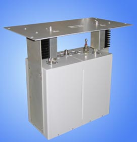
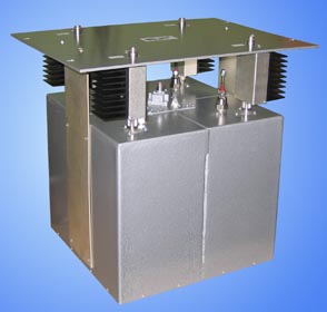
    Low loss transmitter combiner TETRA-4A electric diagram


    The information provided on this page is not an official offer.
    To verify actual parameters contact the sales department before ordering.