|
 

|
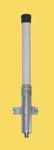
A-3W
(wall mount.)
|
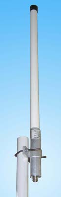
A-7W
|
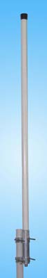
A-10W
 |
| | Electrical specifications
| Model |
A-3W |
A-7W |
A-10W
|
| Operating frequency band, MHz |
2400-2485 |
2400-2485 |
2400-2485
|
| Gain,dBi |
3 |
7 |
10
|
| VSWR, not more than |
2 |
2 |
2
|
| Front-to-back ratio, dB |
present
|
| Polarization |
vertical
|
| Electrical downtilt |
0В° |
6В° |
9В°
|
| Max. power input, W |
10 |
10 |
10
|
| Sector in H-plane (-3 dB) |
360В° |
360В° |
360В°
|
| Sector in E-plane (-3 dB) |
56В° |
14В° |
6.5В°
|
| Impedance, Ohm |
50 |
50 |
50
|
|
|
Mechanical specifications
| Model |
A-3W |
A-7W |
A-10W
|
| Dimensions (LxWxH), mm |
35x35x312 |
35x35x565 |
35x35x1443
|
| Weight with mount kit, kg |
0.3 |
0.47 |
1.1
|
| Rated wind velocity, m/s |
50 |
50 |
40
|
| Radiator |
brass |
brass |
brass
|
| Radome |
Fiberglass, PVC
|
| Mounting |
on a mast diam. 35-70 mm or on a wall
|
| Connector |
N-female
|
| |
These spike antennas possess an ideally circular radiation pattern in horizontal plane and a gain of 3, 7 and 10 dBi, correspondingly. The antenna A-3W is recommended to be applied as the inside-the-office antenna, where it is not possible to use the antennas with high gain. The models A-7W and A-10W have an increased gain and a tilt of the radiation pattern in the vertical plane what ensures the most efficient reception and transmission of SHF energy near the earth surface where the subscribers are positioned. These models are applied in the case of the central disposition of the base station or in the case when the objects are non- significantly distanced.
A-3W E-plane pattern
|
A-7W E-plane pattern (2.485 GHz)
|
A-10W E-plane pattern (2.4 GHz)
|
|
The information provided on this page is not an official offer.
To verify actual parameters contact the sales department before ordering.
|
|