|
 

|
| | Electrical specifications
| Model |
RF8-1UL |
RF8-2UL |
RF10-1UL
|
| Operating Frequency band, MHz |
400-490
|
| Insertion loss (adjustable), dB |
0,5-3 |
1-3 |
0,5-3
|
| Impedance, Ohm |
50
|
| Attenuation (see fig.n) О”f BP/BR=200 kHz, dB |
18 |
35 |
13
|
| VSWR, not more than |
1,5
|
| Input power, not more, W |
not more than 300
|
| Temperature Range with garanted stabilization, В°C |
from -30 to +60
|
| Cavity electrical length |
3/4О»
|
|
|
Mechanical specifications
| Model |
RF8-1UL |
RF8-2UL |
RF10-1UL
|
| Diameter, mm (ins.) |
206 (8") |
257 (10")
|
| Weight, kg |
3,3 |
4,2 |
3,9
|
| Connector |
N-female
|
| Mount to rack |
optional |
19" or |
24"
|
| Length/Width/Depth, mm |
800x206x206 |
800x480x210 |
800x257x257
|
| |
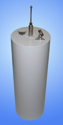
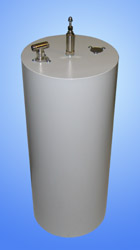
Bandreject filters RF8-UL have found themselves in radio stations and repeaters receiving section operating closely to powerful transmitter, operating at known neighboring frequency. Bandreject filter enables to effectively eliminate interference at significantly lower frequency separation, unlike bandpass filter.
Presence of 3/4-wave cavity in bandreject filter will save your transmitters from persistent signals of paging transmitters or telemetry systems, located closely to your antennas.
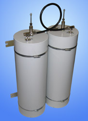
Careful selection of cable junction in RF8-2UL and RF8-3UL filters provides maximum convergence of pass and reject frequency preserving low loss.
Typical selectivity characteristics
RF8-1UL
|
RF10-1UL
|
|
|
The information provided on this page is not an official offer.
To verify actual parameters contact the sales department before ordering.
|
|