 |
 

|
 | | Electrical specifications
| Model |
Insertion
loss, dB |
Input
power, W |
Isolation ANT-TX
not worse, dB |
Diameter of
cavity, mm (ins.) |
Mass, kg |
Temperature
Range, В°C
|
| IMF10-1V-50S-R/2(X/2) |
0.9 |
50 |
30 |
|
4.2 |
|
| IMF10-1V-50D-R/2(X/2) |
1.3 |
50 |
75 |
|
4.35 |
|
| IMF10-1V-125S-R/2(X/2) |
0.9 |
125 |
30 |
|
4.7 |
|
| IMF10-1V-125D-R/2(X/2) |
1.3 |
125 |
75 |
257 (10") |
4.9 |
-30 to +50
|
| IMF10-1V-300S |
0.9 |
300 |
30 |
|
4.85 |
|
| IMF10-1V-300D |
1.3 |
300 |
75 |
|
5.7 |
|
|
|
| |
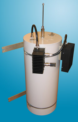
Intermodulation filter IMF10-1V-50S-R/2(X/2), installed in transmitting section, will provide low loss signal passage, attenuate out-of-band transmitters radiation, prevent signals induced to antenna from penetration to transmitter output stage. Application of 10" cavity filter will provide the best out-of-band radiation attenuation and increase isolation of your antenna-feeder system from neighboring transmitters. Installation of single isolator is permitted subject to distance to neighboring antennas makes up 10 О» (across) or 2 О» (in vertical). For shorter distances IMF10-1V-50D-R/2(X/2) with double isolator should be used.
The ferrite isolators of Regular (R) class provide an operation of the intermodulations filters or transmitting link in temporal regime of exploitation with TX/RX =1:5, i.e. when the working load onto the transmitters of your system is not high.
The ferrite valves of Extreme (X) class are being applied in the case when repeaters operate with enhanced load (up to 100% of the cycle). These are more expansive and highly reliable products with the valves based upon the radiators (which do not allow the ferrites to become overheated) and for massive carrying out (external) loads.
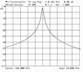
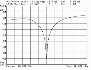
Typical gain-frequency characteristics
filter PF10-1V

|
isolator IF-2V-125

|
|
|
The information provided on this page is not an official offer.
To verify actual parameters contact the sales department before ordering.
|
|


