|
 

|
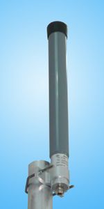
A-8Y
 |
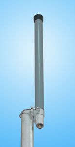
A-11Y
 |
| | Electrical specifications
| Model |
A-8Y |
A-11Y
|
| Operating frequency band, MHz |
5150-5350 |
5150-5350
|
| Gain,dBi |
8 |
11
|
| VSWR, not more than |
1.5 |
1.5
|
| Polarization |
vertical
|
| Electrical downtill |
3° |
7°
|
| Max. power input, W |
10 |
10
|
| Sector in H-plane (-3 dB) |
360° |
360°
|
| Sector in E-plane (-3 dB) |
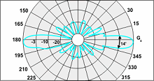
14° |
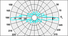
7°
|
| Impedance, Ohm |
50 |
50
|
|
|
Mechanical specifications
| Model |
A-8Y |
A-11Y
|
| Dimensions (LxWxH), mm |
35x35x450 |
35x35x810
|
| Weight, kg |
0.1 |
0.25
|
| Rated wind velocity, m/s |
50 |
50
|
| Radiator |
PCB |
PCB
|
| Radome |
grey PVC |
grey PVC
|
| Mounting kit CPK-70 |
on a mast 35-70 mm or on wall
|
| Connector |
N-female
|
| |
The vertical antennas A-8Y and A-11Y possess an increased gain (8 and 11 dBi), an ideally circular radiation pattern, small electrical tilt of the beam in a vertical plane. Their construction is formed by an antenna array with consequent feeding of the elements on the printed circuit board, implemented on the SHF material, which is characterized by a small value of the dielectric losses. The printed circuit boards are also plated by an SHF-lacquer, and the radome is encapsulated.
A-8Y E-plane pattern
|
A-11Y E-plane pattern
|
|
|
The information provided on this page is not an official offer.
To verify actual parameters contact the sales department before ordering.
|
|