 

|
BR-100-16DR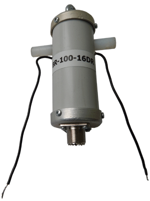
|
BR-100-1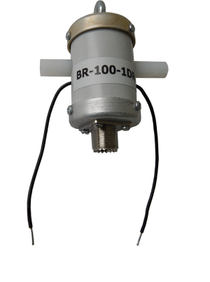
|
| | Electrical specifications
| Operating frequency band, MHz |
1,8-30
|
| Impedance ratio |
|
| BR-100-1 |
1:1-50:50
|
| BR-100-1.5DR |
1:1,5-50:75
|
| BR-100-2.5DR |
1:2,25-50:112
|
| BR-100-4DR |
1:4-50:200
|
| BR-100-6DR |
1:6-50:300
|
| BR-100-9DR |
1:9-50:450
|
| BR-100-16DR |
1:16-50:800
|
| BR-100-20DR |
1:20-50:1000
|
| Impedance, Ohm |
50
|
| Insertion loss, dB |
0.2-0.4
|
Input power, not more, W
(CW, SSB)* |
100
|
| Asymetrict factor no less, dB |
20
|
| Connector |
SO-239
|
| Weight no more, kg |
220
|
| Length/Width/Depth, mm |
140x80x44 (BR-100-1 - 100x80x44)
|
| * The antenna power capacity is defined by the duration of transmission, type of transmission, its frequency, SWR and the ambient temperature.
|
|
|
| |
Based on the accumulated experience in the development, manufacturing and operation of BR-800 series baluns, as well as obtained invaluable experience of selling them to HAMs, we have come to a conclusion that the line of these devices should be complemented with more compact and less powerful models. Currently, the radio amateurs operate from the field using "barefoot" transceiver more and more often, so 100 W of balun passing power is quite sufficient. However, requirements to the dimensions and reliability are high.
Therefore, the following improvements are implemented in our new baluns:
1. All baluns have a cut-off choke. This ensures elimination of the antenna effect and stablizes parameters of field antennas independently of the feeder location.
2. All baluns are manufactured basing on BBRT transformers. This means that the power is passed not by a magnetic field through the core, but over wires that considerably reduces losses of the entire balun.
3. Baluns are completely leak-tight due to the sealing by a two-component compound.
4. Mass of the baluns is reduced due to the decreased dimensions, light-weight plastic enclosure, absence of contact screws, role of which is fulfilled by the conventional multi-core wires.
All baluns pass double inspection using the network analyzers before and after sealing.
The wide range of baluns allows the radio amateurs to manufacture any antennas.
You can examine the baluns usage in the following table:
BR-100-1 Inverted V, half-wave dipole, Yagi, 2 el.Quads
BR-100-1.5DR half-wave dipole
BR-100-2,5DR OCF , 1 el. Quad, W3DZZ
BR-100-4DR Windom, Delta
BR-100-6DR Windom, Delta, loop half-wave dipole
BR-100-9DR aperiodic travelling wave antennas
BR-100-16DR T2FD, Flag, K9AY, Long Wire
BR-100-20DR T2FD
VSWR diagram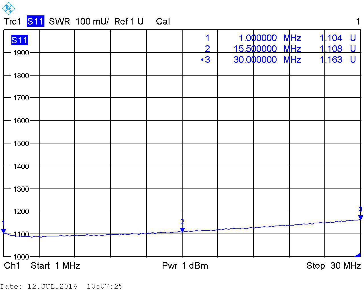
|
|
The information provided on this page is not an official offer.
To verify actual parameters contact the sales department before ordering.
|
|