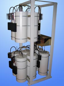
140-174 MHz Low-loss transmitter combiners
www.radial.ru
|


Electrical specifications
| |||||||||||||||||||||||||||||||||||||||||||||||||||||||||||||||||||||||||||||||||||||||||||||||||||||||||||||||||||||||||||||||||||||||||||||||||||||||||||||||||||||||||||||||||||||||||
One should not let go an opportunity to implement cavity transmitter combiners, if frequency separation enables this. This will considerably save radio signal energy, which will be spent in antenna, not in ballast load. Besides, cavities will provide high emission spectrum clearance of your transmitters, reduce noise and spurious radiation, influencing favourably on the air on the whole. Transmitter combiners modular design enables to add additional channels or units for system expansion practically without any insertion loss. Using high-Q cavities and managing insertion loss, we achieve extremely low power loss of signal combining. Complete range of various design cavities and ferrite isolators for various throughputs offers you an opportunity to select transmitter combiner with the best price/loss ratio, planing any antenna-feeder equipment configuration. Submit our engineers with information about frequency plan, power input and output and possible antennas layout and they will help you to determine which transmitter combiner to select. The combiners of Regular (R) class provide an operation of the transmitting link in temporal regime of exploitation with TX/RX =1:5, i.e. when the working load onto the transmitters of your system is not high. The combiners of Extreme (X) class are being applied in the case when repeaters operate with enhanced load (up to 100% of the cycle). These are more expansive and highly reliable products with the valves based upon the radiators (which do not allow the ferrites to become overheated) and for massive carrying out (external) loads. Dependance of loss on frequency separation TX-TX for CL8-4V-50 low loss transmitters combinets
| |||||||||||||||||||||||||||||||||||||||||||||||||||||||||||||||||||||||||||||||||||||||||||||||||||||||||||||||||||||||||||||||||||||||||||||||||||||||||||||||||||||||||||||||||||||||||